Friday, 28 November 2014

Some fact about maglev ( magnetically levitated)

MAGLEV

Magnetically levitated (MAGLEV) trains are considered as a future application of HTS development. To understand why, we must look briefly at the history of the railroads. The development of trains and rails began in the early 1800s. The modern conventional train is no faster (~110 mph) than those of the late 1890s. So conventional trains have reached the end phase of their development.
France, Germany, and Japan have developed "high-speed" or "bullet" trains capable of speeds of 150-180 mph. This improvement in speed is based upon improved rails and controls. However, this technology has also reached the end phase of its development. One limiting factor for these trains is the expensive and time-consuming maintenance of the rails. So it is the mechanical friction between train wheels and metal tracks that limit this technology. This leads us to the development of the magnetically levitated (no friction) trains. We briefly describe the history of this development.
 Superconductivity Technology Center - magnetic levitation trainsThe idea of MAGLEV transportation has been around since the early 1900s. The benefit of eliminating the wheel/rail friction to obtain higher speeds and lower maintenance costs has great appeal. The basic idea of a MAGLEV train is to levitate it with magnetic fields so there is no physical contact between the train and the rails (guideways).
To get from this simple concept to a real operational system involves enormous technological developments. While there has been no development of MAGLEV trains in the U.S., in Germany and Japan they have developed functioning demonstration trains (in Japan they have one system that has transported over a million people). To date there are no existing construction designs that include HTS magnets, but we will give a brief history of the MAGLEV trains in Japan and Germany to help explain why HTS magnets should be considered in future development.
Two basically different concepts of magnetic suspension have evolved.
  1. The attractive electromagnetic suspension (EMS) uses electromagnets on the train body which are attracted to the iron rails. The vehicle magnets wrap around the iron guideways and the attractive upward force lifts the train.
  2. The electrodynamic suspension (EDS) levitates the train by repulsive forces from the induced currents in the conductive guideways.
In both of these systems the levitating magnets are mounted to a number of "bogies" connected to the train body by a secondary suspension system of dampers and springs. However there is a fundamental difference between these two systems. In the EMS system, the "airgap" between the guideways and train magnets is very small (~1/2 inch), whereas the "airgap" in the EDS system may be as large as 8-10 inches. The small airgap of the EMS system implies much more stringent controls to maintain this small gap.
The superconducting magnets that have been used in these MAGLEV systems have been of the low temperature variety. Because these must operated below liquid helium temperature (4.2 K) these are expensive and complex systems. The technological advantage of operating HTS magnets at liquid nitrogen temperatures (77 K) are enormous.

electric-powered diwheel

  • electric-powered diwheel


World, Meet EDWARD. This electric-powered diwheel is a project created by engineering students at the School of Mechanical Engineering at the University of Adelaide in Australia.
edward

The designers say

Many diwheels in the past have been human powered or powered by IC engines. This one is purely electric. It has additional functionality lacking in other models, including inbuilt dynamic lateral stability and slosh control to prevent "gerbiling" or tumbling in aggressive braking or acceleration maneuvers. The diwheel also incorporates a unique feature that allows the rider to drive the vehicle when "upside down" - keeping the vehicle in its unstable state is achieved using a combined swingup and inversion controller.
edward

Overview

The EDWARD Project was begun in 2009 as an honours project for undergraduates in the Adelaide engineering program. It completed in December 2010 with most of the design mechanicals being done in 2009 and the electronics and control systems done in 2010.
EDWARD stands for Electric Diwheel With Active Rotation Damping. The idea behind the project was to make the diwheel not only stable at all times, but also capable of some real acrobatic feats. The final version of EDWARD is able to drive in all directions perfectly level, spin horizontally in place, "rock" without moving, "gerbil" (spin vertically in place), and even be driven with the driver upside down.
Part of the inherent design in EDWARD is its relatively high center of gravity, which in a production version for mass consumption would not be the case. This was meant to challenge students in their control systems designs. Because of this high center of gravity, the diwheel is capable only of light gradients (around 12 degrees or less) and has a long brake time compared to a bicycle or car of similar mass. All of this would change with a lower CoG.
EDWARD can get up to 40km/hr in speed and has a battery life of about an hour under aggressive conditions. It's batteries are lead acid.
Students demonstrating the capabilities of the machine can be seen in this video:

Although EDWARD will never make it to production and was meant only as a class project, it is still a very cool machine. Fans of Star Wars may remember the diwheels featured in the films (called the Hailfire Droid), which were the inspiration for the project that became EDWARD.
The Adelaide students and EDWARD were featured on Australia's Top Geartelevision program and showed the machine at two MechExpo events and other shows in Australia.
The design challenges are interesting and as a commercial product, it's obvious that a small market of people would be interested in these as a toy and something to get around the neighborhood with. The unique driving capabilities and acrobatics that can be safely enjoyed with the diwheel design are obvious.
This author sees these as a potential kit car that many people would clamor to purchase and put together in their own garages.

Facts About Future Electric Cars

Basics

All-electric cars, a.k.a. electric vehicles (EV) or battery electric vehicles (BEV), are propelled purely by means of an electric motor powered by an on-board battery (to be precise, the battery powers a controller which in turn powers the motor). The battery can be recharged using a standard electrical outlet or at a charging station

Motor Types

AC Motors
Virtually all of the EV's and hybrids on the market use AC motors. Alternating-Current motors are better for continuous power (hills). Starting power is slower, but the motor can run at high RPMs without overheating. Because they can run at high RPMs they do not require a transmission. They can also move a heavier vehicle.
AC motors are best suited to the regenerative braking systems featured in both EVs and hybrids. Regenerative braking, which returns braking power to the battery, combined with superior efficiency make for better fuel economy. Generally speaking, AC motors run more smoothly and can be precisely controlled. For these reasons, production model electric cars and hybrids use AC motors.
AC motors have significant disadvantages, particularly for the DIY hobbyist. They are more expensive than DC Motors and so are the battery packs. They are also more complicated to control. Because battery output is DC, they require a converter which takes up a lot of space.
DC Motors
Though the debate rages on, about the pros and cons of AC vs DC, DC Motors are the favorite choice of DIYers who convert their gas-powered cars to electric. DC motors are more affordable and easier to control. They also have greater initial torque and higher peak power, so they are popular with racers.
A major disadvantage of DC motors is a tendency to overheat. They also become very large and heavy according to their power output.
AC conversion kits are now available and will become more popular for conversions. However, there are a wide variety of DC motor designs which may improve for EV application.

Battery types

Batteries are the greatest obstacle to the proliferation of EVs. Electric cars require a lot of batteries which must be installed in an array and housed in a battery pack. These batteries are heavy (the Tesla Roadster's battery pack weighs 1,000 lbs) and take up a lot of cubic centimeters. Then there is the simple fact that batteries run out of power and must be recharged.
"But regular cars have to be refueled," you might say. True, but if we're going to replace gas stations with charging stations we're going to have a parking problem because batteries take a long time to recharge.

Three types of batteries are found in electric cars:

Lead-acid batteries
Oldest type of rechargeable battery. Cheap to produce and compatible with existing electronics. Messy, toxic and prone to explosion.
Lithium ion batteries [Li-ion]
High energy-to-mass ratio (which means less weight per unit of stored energy). They retain their stored energy when not in use but lose capacity with age. Considered to have the most potential for mass-market EVs but the most advanced models are too expensive. NiMH batteries are toxic and require special handling to recycle.
Nickel metal hydride [NiMH]
Good energy-to-mass ratio (a.k.a. energy density). Non-toxic which makes for easy recycling. The major disadvantage to nickel metal hydride batteries is that they don't hold a charge very well when they aren't being used.
The problems with battery technology explain why there is so much excitement around fuel cells. Compared to batteries, fuel cells will be smaller, much lighter and instantly rechargeable

A Trick for Making Batteries Safer Could Also Make EVs Affordable

A Trick for Making Batteries Safer Could Also Make EVs Affordable


Bulky and expensive batteries are the bane of electric vehicles. A new MIT spinoff company,SolidEnergy, says it has a solution: materials that can increase the amount of energy that lithium-ion batteries store by 30 percent or more and lower costs enough to make electric vehicles affordable.
The startup recently raised $4.5 million in its first round of venture funding. It is working with A123 Venture Technologies, part of the battery maker A123 Systems, to scale up the technology and bring it to market.
SolidEnergy replaces the graphite electrode used in conventional lithium-ion batteries with a high-energy lithium-metal one. That’s been tried before, but the metal tends to cause short circuits and fires. So the company has also developed improved electrolytes to make them safer. It plans to sell materials to battery manufacturers, rather than making batteries itself.
So far, SolidEnergy has made small, hand-built battery cells, similar to what you would find in a cell phone, using equipment and experts at an A123 Systems lab near Boston. (A123 Systems went bankrupt last year, and was acquired by the Chinese company Wanxiang.) These experimental cells store 30 percent more energy than conventional lithium-ion batteries, but the company calculates that the approach could eventually lead to a 40 percent improvement.
The first application of the technology will likely be in portable electronics, says cofounder and chief technology officer Qichao Hu. Electric vehicle batteries take longer to develop, in part because they need to last a decade, whereas batteries for powering electronics need only last a few years (see “How Tesla Is Driving Electric Car Innovation” and “Will Electric Vehicles Finally Succeed?”).
Lithium-metal electrodes are used in some specialty batteries now, but the measures that battery makers use to prevent short circuits weaken the batteries’ performance and increase the cost of making them. Typically researchers replace the liquid electrolytes used in conventional lithium-ion batteries with solid polymer ones, which are poor conductors of lithium ions, and have to be heated up to work properly.
SolidEnergy uses a two-part electrolyte. First, it coats the lithium metal with a thin polymer, much like the solid electrolyte others have used. The key difference is that it’s very thin, so it doesn’t slow down lithium ions, and the battery doesn’t need to be heated. The thin polymer can be applied using conventional electrode-coating equipment, Hu says. On its own, the thin polymer isn’t enough to prevent short circuits, so he supplements it with a liquid electrolyte.
Unlike conventional liquid electrolytes, the ones SolidEnergy is using—they’re a type of what’s known as an ionic liquid—are not flammable, which improves safety. In some recent, highly publicized battery fires, the part that was burning was primarily the electrolyte (see “What the Tesla Battery Fire Means for Electric Vehicles” and “Musk is Wrong to Say Tesla’s Model S is Less Likely to Catch Fire than Conventional Cars”).
SolidEnergy calculates that its materials could be used to make battery packs that cost $130 per kilowatt-hour, in line with U.S. Department of Energy goals for making electric vehicles affordable. Battery pack costs are typically kept secret, but estimates range from $250 to $500 per kilowatt-hour for packs in commercial electric vehicles.
It’s difficult to judge SolidEnergy’s claims, because it isn’t making any data about its cells public, says Jeff Dahn, professor of physics and chemistry at Dalhousie University. He says a major question is how many times the batteries can be recharged. Another significant challenge will be reducing the cost of the ionic liquid electrolytes, which are expensive in part because they’re made in low 

5 Reasons to Promote Li-Fi Technologies

5 Reasons to Promote Li-Fi Technologies


Li-Fi logoAlthough the use of light in order to transmit data can be limited in comparison to radio waves, there is a great amount of possibilities that can be developed due to this technology. In essence, a single pixel of a monitor could transmit a single channel of information to a source. Although this technology is still in its infant stages, the usefulness of this Li-Fi technology has implications for a great amount of good.
1. Distance - The sheer range of transmitting information could be worth the decrease in data speeds. The RONJA project in the Czech Republic can transmit a 10 Mbit/s Ethernet-type link just under a mile. As developments of this aspect continue, the range could be entirely up to the strength of the light which is emitting the information. Although the speeds are less than what they are for gigabit Ethernet, the power of the beam can allow DVD-quality streaming of video to any location connected to the Li-Fi device.
2. Cost - Instead of running close to a mile worth of cable, the LED-powered Li-Fi connection could be used to beam the information directly to the destination. Using a point-to-point array, office buildings can stay connected to each other without the use of additional cables being laid from one access point to another. The only problem the two buildings would be faced with is obstruction by solid objects or dense weather patterns such as heavy fog or snow.
3. Traffic Updates - Could you imagine having a car that uses a GPS system that receives information from traffic lights informing you of accidents and/or delays up ahead? There is a kind of system like that already in play for GPS navigational systems, but the traffic lights could be updating drivers using basic information or streaming video directly from news broadcasts.
4. Game Consoles - An innovative idea would be to put sensors on a television in order to receive information from game consoles. This would allow the unit to be place literally anywhere within the room as long as there is a direct line of sight to the sensor. Could you imagine a game system like the Xbox using a Kinect and all of it being completely wireless except for the power going into the unit? That will be tackled once wireless energy is perfected for practical home use.
5. Television Interaction - Instead of using apps or additional installations, you could theoretically hold your phone up as you sit on the couch and have every piece of information regarding the show or movie you are currently watching sent to your display – even recording directly to your mobile device. Of course, this may spawn some kind of copyright lawsuit because you are illegally copying a movie or television show, but you still get the idea. There are a number of reasons why investing in Li-Fi technology can have a great benefit to the future of wireless networking. Although there are a few aspects that need to be ironed out before it can be introduced on a wide scale of practicality, the future looks to be very promising. Even if the technology was merely developed as a small scale indoor application to “beam” information directly to a computer system without the use of Ethernet cable being strewn about the floor, visible-light communications could set the benchmark higher for wireless transmissions.

Programmable Logic Controllers

Programmable Logic Controllers


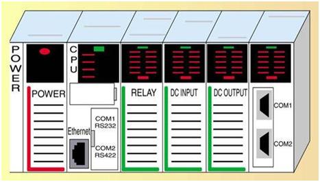
PLC stands for Programmable Logic Controllers. They are basically used to control automated systems in industries. They are one of the most advanced and simplest forms of control systems which are now replacing hard wired logic relays at a large scale.
PLC
Programming Logic Controller (PLC)

Advantages:

Before getting into details about PLCs, lets us know 3 reasons why PLCs are being widely used these days
  • They are user friendly and easy to operate
  • They eliminate the need for hard wired relay logic
  • They are fast
  • It is suitable for automation in industries.
  • Its input and output modules can be extended depending upon the requirements

PLC Architecture:

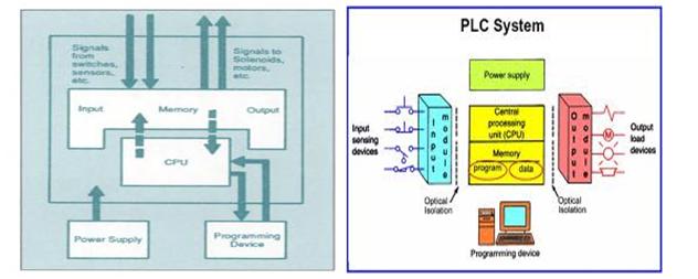
PLC Internal Architecture
A basic PLC system consists of the following sections:
  • Input/ Output Section: The input section or input module consists of devices like sensors, switches and many other real world input sources. The input from the sources is connected to the PLC through the input connector rails. The output section or output module can be a motor or a solenoid or a lamp or a heater, whose functioning is controlled by varying the input signals.
  • CPU or Central Processing Unit: It is the brain of the PLC. It can be a hexagonal or an octal microprocessor. It carries out all the processing related to the input signals in order to control the output signals based on the control program.
  • Programming Device: It is the platform where the program or the control logic is written. It can be a handheld device or a laptop or a computer itself.
  • Power Supply: It generally works on a power supply of about 24 V, used to power input and output devices.
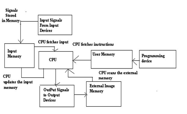
  • Memory: The memory is divided into two parts- The data memory and the program memory. The program information or the control logic is stored in the user memory or the program memory from where the CPU fetches the program instructions. The input and output signals and the timer and counter signals are stored in the input and output external image memory respectively.
Working of a PLC
PLC Working Schematic
PLC Working Schematic by Edgefx Kits
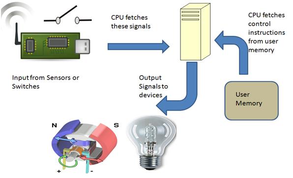
Working of PLC
Working of PLC by Edgefx Kits
  • The input sources convert the real time analog electric signals to suitable digital electric signals and these signals are applied to the PLC through the connector rails.
  • These input signals are stored in the PLC external image memory in locations known as bits. This is done by the CPU
  • The control logic or the program instructions are written onto the programming device through symbols or through mnemonics and stored in the user memory.
  • The CPU fetches these instructions from the user memory and executes the input signals by manipulating, computing, processing them to control the output devices.
  • The execution results are then stored in the external image memory which controls the output drives.
  • The CPU also keeps a check on the output signals and keeps updating the contents of the input image memory according to the changes in the output memory.
  • The CPU also performs internal programming functioning like setting and resetting of the timer, checking the user memory.

Programming in PLC

The basic functioning of the PLC relies on the control logic or the programming technique used. Programming can be done using flowcharts or using ladder logic or using statement logics or mnemonics.
Interlinking all these, let us see how we can actually write a program in PLC.
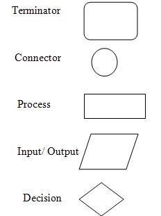
  • Compute the flowchart. A flowchart is the symbolic representation of the instructions. It is the most basic and simplest form of control logic which involves only logic decisions. Different symbols are as given below:
Compute the flowchart
  • Write the Boolean expression for the different logic. Boolean algebra usually involves logic operations like AND, OR, NOT, NAND and NOR. The different symbols are:
+   OR operator
.     AND operator
!     NOT operator.
  • Write the instructions in simple statement forms like below:
IF Input1 AND Input2 Then SET Output1 ELSE SET Output
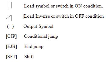
  • Write the ladder logic program. It is the most important part of PLC programming. Before explaining about ladder logic programming, let us know about few symbols and terminologies
Rung: One step in the ladder is called a rung. In simpler words, the basic statement or one control logic is called a Rung.
Y- Normal Output signals
M – Motor symbol
T – Timer
C – Counter
Symbols:
Symbols
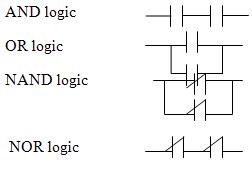
Basic Logic Functions using Ladder Logic
Basic logic functions using ladder logic
  • Writing Mnemonics: Mnemonics are instructions written in symbolic form. They are also known as Opcode and are used in handheld programming devices. Different Symbols are as given below:
Ldi – Load Inverse
Ld- Load
AND- And logic
OR- Or logic
ANI – NAND logic
ORI- NOR logic
Out – Output

A Simple PLC Application

So, now that we have had a brief idea about programming in PLC, lets get into developing one simple application.
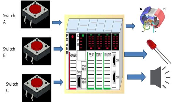
Problem: Design a simple line follower robotic system to start a motor when a switch is on and simultaneously switch on the LED.  The sensor on the motor detects any obstacle and another switch is on to indicate the presence of the obstacle and the motor is simultaneously switched off and the buzzer is switched on and LED is off.
Solution:
Solution
Solution by Edgefx Kits
Let us first assign our symbols or tags to the inputs and outputs
M – Motor  ,
A – Input Switch 1  ,
B- Input Switch 2 ,
L – LED ,
Bu –Buzzer
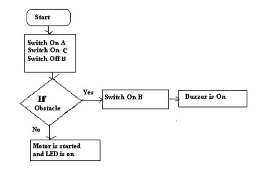
Now let us design the Flow Chart
flow chart
Flowchart for the Design by Edgefx Kits
Next Step is writing the Boolean expressions
M = A. (! B)
L = C. (! B)
Bu = B. (! A.! C)
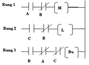
The next step involves drawing the ladder logic program
Ladder Logic Program
Ladder Logic Program by Edgefx Kits
The final step involves writing the mnemonics to be fed to the handheld device
Ld A ANI Ldi B
Ld C ANI Ldi B
Ld B ANI Ldi A AND Ldi C
So, now that I have demonstrated the basic control function using PLC, do let me know more about the ideas of control designs using PLC.

LED lamps: less energy, more light

LED lamps: less energy, more light

LEDs are durable and save energy. Now researchers have found a way to make LED lamps even more compact while supplying more light than commercially available models. The key to success: transistors made of the semiconductor material gallium nitride.
Incandescent light bulbs are now banned in the EU, while energy-saving lamps remain a bone of contention. In 2016, it will be lights out for halogen bulbs over 10 watts as well. LEDs (light-emitting diodes) therefore have the best chance of becoming the light source of the future. Experts reckon that LED retrofit lamps for use in standard bulb fittings will overtake traditional energy-saving bulbs for the first time from 2015. By 2020 it is predicted that LEDs will have captured between 88 and 90 percent of the lighting market. The tiny diodes offer a whole host of advantages as the most environmentally friendly source of light – they contain no harmful substances, consume less energy and, with a lifetime of between 15,000 and 30,000 hours, last longer than conventional light sources. They also work at full brightness as soon as you flick the switch.

Coping with higher temperatures

LEDs do have one weakness, though – they are extremely sensitive to variations and spikes in power. To function properly, they need a driver that ensures a constant supply of power at all times. This driver, which takes the alternating current from the grid and converts it into direct current with a reduced voltage, has a profound influence on the light yield and lifetime of the LED lamp as a whole. The demands placed on the driver electronics are correspondingly high. This has prompted researchers at the Fraunhofer Institute for Applied Solid State Physics IAF in Freiburg to focus their attention on voltage transformers featuring gallium nitride (GaN) transistors. During practical testing, the scientists found that the drivers developed using this new semiconductor material were extremely robust. Components made of GaN can operate at higher currents, voltages and temperatures than standard silicon transistors. “Heat plays a role both in the brightness and the service life of LED lamps,” says Dr. Michael Kunzer, group manager at Fraunhofer IAF.

Gallium nitride transistors switch at high speed


Gallium nitride transistors can also switch at high frequencies. The switching speed has a significant impact on the size of the coils and condensers built into the drivers for energy storage. In a GaN-based driver, the switch speed can be made as much as a factor of 10 faster than that of its silicon equivalent. “Applied to a smaller surface, this means it is possible to make switching cheaper. The whole LED lamp can be made lighter and more compact while delivering the same or even improved illumination,” explains Kunzer. Since the energy storage component plays a decisive role in manufacturing costs, this could have an extremely positive effect on the end price.

Thanks to the new semiconductor material’s useful properties, Kunzer and his team have been able to boost the efficiency of the GaN driver to 86 percent – between one and four percentage points better than its silicon equivalent. When compared with the silicon transistor LED lamps available on the market., the scientists were able to increase the light output: while the luminous flux of commercial LED retrofit lamps featuring silicon components is around 1000 lumen (the unit used to measure the light produced), researchers from the IAF have been successful in increasing this to 2090 lumen. “20 percent of energy consumption worldwide can be attributed to lighting, so it’s an area where savings are particularly worthwhile. One shouldn’t underestimate the role played by the efficiency of LED drivers, as this is key to saving energy. In principle, the higher the light yield and efficiency, the lower energy consumption is. If you think that by 2020 LEDs will have carved out a market share of almost 90 percent, then it is obvious that they play a significant role in protecting our environment,” says Kunzer. The researchers will be showcasing a demonstrator of their retrofit LED from April 7-11 at the Hannover Messe, where they can be found at the joint Fraunhofer booth in Hall 2, Booth D18.
file to be dowloaded: