Friday, 28 November 2014

Particulate sensor developed using open source approach

Particulate sensor developed using open source approach

Particulate sensor developed using open source approach


A New York based start up company has used an open source approach, as well as funding from Kickstarter, to develop AirBeam – a handheld sensor which determines the concentration of particles in the air measuring 2.5µm or less. 
According to AirCasting, PM2.5 is one of the six air pollutants monitored and regulated by the US Environmental Protection Agency. It's also a figure of interest to the EU, which has set a requirement that PM2.5 concentrations should not exceed 25µg/m3.

The reason for the concern is that these particles – produced from sources such as diesel car exhausts – are small enough to pass through the lungs and enter the bloodstream, with adverse health effects.

AirBeam, developed with Sonoma Technology and New York University's School of Medicine, draws air into a sensing chamber, where light from an LED is scattered from the particles in the air. A detector then estimates the number of particles in the air.

This data is transmitted once per second via Bluetooth to the AirCasting app on an Android phone, where it is graphed in real time. Areas with higher PM2.5 concentration are shown in red.

At the end of each AirCasting session, the collected data is sent to the AirCasting website, where the data is used to generate maps showing where PM2.5 concentrations are highest.

The company also plans to develop LiteBeam. This hand held device, which is built around the PIC microcontroller based IOIO board, takes data from the AirCasting app via Bluetooth and illuminates green, yellow or red LEDs, according to the concentration.

The AirCasting app and website code is available on GitHub as open source, along with the AirBeam firmware and electronic schematics.
For more information on open source sensor software - click here

Metal Detector Robotic Vehicle

Land mines buried under the ground causes threat to the lives and affect the economy of the nation. Detection and removing of these mines manually is a dangerous task, which may sometimes causes accidents. In such situations robots aid in detection of the land mines. Not only  land mines, these robots can be used to detect any other metals presented in the ground. This article explains the metal detection robot that uses RF technology. Before going to know about this metal detector robotic vehicle, get an idea about how a metal detector circuit works

Wireless Metal Detector Robot Circuit Principle:

The proposed system consists of transmitter and receiver circuit. The transmitter circuit transmits the commands required to operate the robot. The receiver circuit receives these commands through RF and moves the robot according to the received commands. A metal detector is interfaced to the controller in the receiver side. Thus whenever any metal is detected the robot stops there and buzzer starts ringing.

Wireless Metal Detector Robot Circuit Diagram:

Transmitter Circuit:

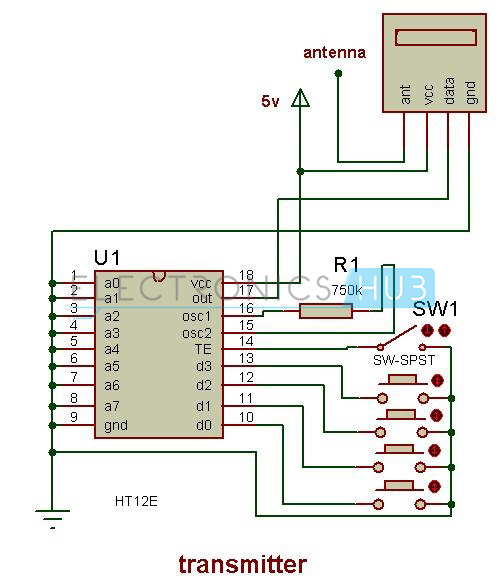
Metal Detector Robot - Transmitter
Metal Detector Robot – Transmitter

Receiver Circuit: 

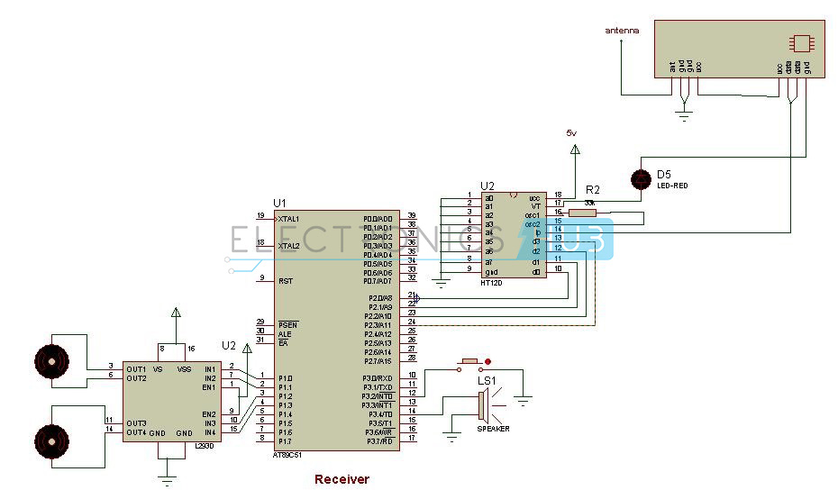
Metal Detector Robot - Receiver Circuit
Metal Detector Robot – Receiver Circuit
Circuit Components:
Hardware Components:
  • AT89c51 microcontroller.
  • RF encoder and decoder
  • RF transmitter and receiver pair.
  • Push buttons.
  • Buzzer.
  • Robot.
  • L293d
  • Rs 232 cable.
Software Components:
  • Keil software
  • Flash magic
  • Proteus.

Circuit Design of Metal Detector Robot using Microcontroller:

The metal detection robot project can be divided into sections 1) Transmitter section, 2) Receiver section.
The transmitter section consists of RF encoder, RF transmitter and Push buttons. RF encoder IC used here is HT12E.It is an 18 pin IC .The 4-bit binary input is applied to the decoder through the AD0, AD1, AD2, AD3 pins. The TE pin enables the transmission when it is low.A0-A7 are the address pins used for secured transmission. These pins are connected to ground in the transmitter circuit. The 4-bit data is transmitted to the RF transmitter parallelly. This is transmitted to the RF receiver serially. Input is given to the encoder through buttons. The RF pair operates with a frequency of 434 kHz.
Receiver section consists of AT89c51 microcontroller, RF decoder, RF receiver, metal detector, buzzer, L293d IC and robot.
The data received is applied to the RF decoder. The RF decoder used here is HT12D. Decoded inputs are connected port 2 of the microcontroller. The four data pins D0-D3 are connected to the Port P2.0 – P2.3.The decoded data is applied to the microcontroller which controls the movement of the robot. The buzzer is connected to the port 3.4 and this rings when any metal is detected in its path.
 Metal detector is connected to the pin 3.2 of the microcontroller. Here in place of metal detector a push button is connected. Metal detector plays a main role in the circuit. This will have an oscillator inside it, which produces an alternating current that passes through the coil producing an alternating magnetic field. When any metal is present near the coil this induces magnetic field and thus it can be detected by using another coil which detects the change in the field.
L293d is a motor driving IC .This IC is used to drive the motors.L293d has h-bridge internally. To know more about this IC refer L293D Datasheet.

RF based Metal Detector Robot Circuit Simulation:


Wireless Metal Detection Robot Circuit Working:

  • Initially burn the code into the microcontroller using flash magic.
  • Now switch on the power supply for the circuit.
  • Now send the command ‘1’ using the transmitter.
  • This is transmitted to the receiver.
  • At the receiver side receiver receives these commands and moves the robot according to the commands.
  • The following commands moves the robot in the specified directions
    • Forward
    • Backward
    • Left
    • Right
  • While robot is moving if any metal is detected in its path, the robot stops there ringing the buzzer.
  • Again it starts moving when the commands are sent from the transmitter. 

Metal Detector Robot Circuit Algorithm:

  • Initially, declare port2 as input as this is connected to the decoded input.
  • Now declare port1 as output as the motor pins of the robot are connected to the port1.
  • Enable the external interrupt.
  • Now check the input of port2.
  • If the received value is equal to 1 then move the robot in forward direction by making port value as 0×01.similarly move the robot according to the input value.
  • When interrupt occurs make the output pins to the motor low. This is written in ISR. 

Microcontroller based Metal Detector Robot Applications:

  • These robots are used in detecting landmines.
  • Robots are used for in detecting the minerals present in the ground.
  • These robots are used for detecting the bombs.
  • These can be used in construction industry  for locating steel bars present in concrete.
  • They are used in airports and building security to detect the weapons. 
Limitations of the Circuit:
The transmitter can operate the robot only in the range of RF that is approximately 30 metres.

100W MOSFET Power Amplifier Circuit

100W MOSFET Power Amplifier Circuit

A power amplifier circuit using MOSFET has been designed to produce 100W output to drive a load of about 8 Ohms.  The power amplifier circuit designed here has the advantage of being more efficient with less cross over distortion and total harmonic distortion.

Principle of Operation:

This circuit operates on the principle of multi-stage power amplification consisting of pre amplifiers, drivers and power amplification using MOSFET.  The pre amplification is done using a differential amplifier, driver stage is the differential amplifier with current mirror load and power amplification is done using MOSFET class AB operation. MOSFETs have an advantage over BJT in having a simple drive circuit, being less prone to thermal stability and having high input impedance. A pre-amplifier consisting of a two stage differential amplifier circuit is used to produce a noise free amplified signal.  First stage of the pre-amplifier consists of a differential mode emitter coupled amplifier using PNP transistors. The second stage consists of a differential amplifier with active load, so as to increase the voltage gain. The current mirror circuit actually ensures the output current to remain constant irrespective of the changes in input signal voltages. This amplified signal is then given to the push pull amplifier stage, which produces a high power output signal.

100W MOSFET Power Amplifier Circuit Diagram:

100W MOSFET Power Amplifier Circuit Diagram
Circuit Diagram of 100W MOSFET Power Amplifier 
Components of the Circuit:
  • R1, R4:  4k ohms
  • R2: 100 ohms
  • R3: 50k ohms
  • R5: 1k ohms
  • R6: 50k ohms
  • R7: 10k ohms
  • R8, R9: 100 ohms
  • R10, R13: 470 ohms
  • R11: 100 ohms
  • R12: 3k ohms
  • R14, R15: 0.33 ohms
  • C1:  10uF
  • C2, C3: 18pF
  • C4: 100nF
  • Q1, Q2:  BC556, PNP transistors
  • Q3, Q4:  MJE340, NPN transistors
  • Q5, Q6: MJE350, PNP transistors
  • Q7: n channel E-MOSFET, IRF530
  • Q8: p channel E-MOSFET, IRF9530
  • V1, V2: +/- 50 V

MOSFET Power Amplifier Circuit Design:

1st Stage Differential Amplifier Design:
  1. Selection of Emitter Resistors:  For an efficient differential amplifier, the common mode rejection ratio given by R3/R2 should be higher. This requires the value of R2 to be much lower than R3. Here we select a 100 ohm potentiometer as R2 and 50k resistor as R3.
  2. Selection of Collector Resistors: For a differential gain of around 50 and emitter resistance about 100 Ohms, the value of R1 and R4 is calculated to be about 4k.
  3. Selection of Coupling Capacitor: Here we select a capacitor of 10uF to couple the AC input signal to the input of Q1.
2nd Stage Differential Amplifier Design:
  1. Selection of R11: For a total emitter current of around 0.5A, the value of emitter resistance is chosen to be around 100 ohms.
  2. Selection of R12:  The value of potentiometer R12 is determined by the Gate threshold voltage of MOSFETs and the quiescent current flowing through the collector of Q4, which is around 50mA. This gives R12 to be around 3k.  Similarly value of R7 is taken to be around 10k.
  3. Selection of Load: Here the differential amplifier is connected to an active load, which is a current mirror circuit. Here we select PNP transistors MJE350 with emitter resistors 100 ohms each. The emitter resistors are selected for a approx voltage drop of 100mV across them to ensure decent matching of the transistors.
Power Amplifier Output Stage Design:
Here we select N channel MOSFET IRF530 and P channel MOSFET IRF9530 as power amplifiers. For a power of 100w and load of 8 ohms, required output voltage is about 40V and output current is about 5A.   This gives the value of source resistors to be around 0.33 ohms and the current drawn by each MOSFET to be around 1.6A (output voltage/(pi multiplied by load resistance)).

100W MOSFET Power Amplifier Circuit Operation:

PNP transistors form the differential amplifier circuit where one of the transistors receives the input AC signal and the other transistor receives the output signal through feedback.   The AC signal is coupled to the base of Q1 through coupling capacitor and feedback signal is fed to the base of Q2 through R5 and R6. The output of the amplifier is set by adjusting the potentiometer. The output from the first stage differential amplifier is fed to the input of the second stage differential amplifier.  When input voltage is more than the feedback voltage (in case of the first differential amplifier), the voltage inputs to the transistors Q3 and Q4 of the second differential amplifier simultaneously differs from each other.   The transistors Q5 and Q6 form the current mirror circuit. This current mirror circuit ensures the output current flowing to the push pull amplifier circuit to remain constant.
This is achieved because when collector current of Q3 increases, the collector current of Q4 decreases to maintain a constant current flowing through the common point of the emitter terminals of Q3 and Q4.
Also the current mirror circuit produces an output current equal to the collector current of Q3. The potentiometer R12 ensures the application of proper DC biasing to each MOSFET. Since the two MOSFETs are in complementary to each other, when a positive voltage is applied to the gate of Q7, it conducts. Similarly for a negative threshold voltage, Q8 conducts. The gate resistors are used to prevent the MOSFET output from oscillating.
The input to the circuit is given by a 1khz AC input voltage of 4Vp-p.  An oscilloscope is connected such that channel A is connected to input and channel B is connected to output. The power at the load is observed by connecting a wattmeter to the load.

Applications of 100w MOSFET Power Amplifier Circuit:

  1. It can be used to drive audio loads like loudspeaker, as an audio amplifier.
  2. It can be used to drive RF loads like high power antenna.
  3. It can be used to implement a distributed speaker system
  4. This circuit can be used in electronic devices like televisions, computers, mp3 players etc.
Limitations of this Circuit:
  1. MOSFET is more prone to electrostatic discharge.
  2. The MOSFET draws quite high current from the supply, which can damage the whole circuit, unless safety fuses are used.
  3. This circuit is prone to high frequency oscillations.
  4. This circuit is a theoretical circuit and is for education purpose.

Metal Detector Circuit

Metal Detector Circuit

Introduction:
Metal detector is very common devices for checking the person in shopping malls, hotels, cinema halls to ensure that person is not carrying any explosive metals or illegal things like guns, bombs etc. metal detectors can be created easily and the circuit is not that complex.

Block Diagram of Metal Detector:

Metal Detector - Block Diagram
The LC circuit is nothing but inductor and capacitor which is connecter in parallel. The LC circuit will trigger the proximity sensor if it detects any metal near to it. Proximity sensor will give glow the led, and also make the buzz with the help of the buzzer.
Main Components in Metal Detector Circuit:
LC CIRCUIT: LC Circuit is a resonating circuit which will resonate when exact same frequency material comes near. The LC circuit consist of inductor and capacitor connected in parallel , when the capacitor is fully charged the charge of the capacitor will be given to the inductor, here inductor will have improve its magnetic field. After some time the capacitor will have no charge and current from the inductor will be given to the capacitor in a reverse polarity and capacitor will get charge and now the inductor magnetic field and current will become nil. Again charged capacitor will give current to the inductor to improve its magnetic field. Note inductor is a magnetic field storage device and capacitor is electric field storage device.
PROXIMTY SENSOR: The proximity sensor can detect the objects with out any physical interference. The proximity sensor will work same as infrared sensor, proximity also release a signal, it will not give output unless and until there is no change in the reflected back signal, If there is a change in signal it will detect and give the output accordingly. There are different proximity sensors for example to detect plastic material we can use capacitive type proximity and for metals we should use inductive type.

Circuit Diagram of Metal Detector:

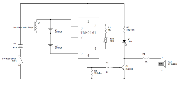
Metal Detector - Circuit Diagram

Metal Detector Circuit Explanation:

  • When the LC circuit that is L1 and C1 has got any resonating frequency from any metal which is near to it, electric field will be created which will lead to induces current in the coil and changes in the signal flow through the coil.
  • Variable resistor is used to change the proximity sensor value equal to the LC circuit, it is better to check the value when there is coil not near to the metal. When the metal is detected the LC circuit will have changed signal. The changed signal is given to the proximity detector (TDA 0161), which will detect the change in the signal and react accordingly. The output of the proximity sensor will be of 1mA when there is no metal detected and it will be around 10mA when coil is near to the metal
  • When the output pin is high the resistor R3 will provide positive voltage to transistor Q1. Q1 will be turned on and led will glow and buzzer will give the buzz. Resistor r2 is used to limit the current flow.

DTMF Controlled Robot without Microcontroller

DTMF Controlled Robot without Microcontroller

DTMF is the acronym for Dual tone modulation frequency. Robotic vehicle based on DTMF technology is explained in this article. Here is a circuit that operates the robot without using a microcontroller. This circuit consists of simple ICs.
When a key is pressed from our mobile, it generates a tone combination of two frequencies from our keypad. In the two frequencies, one is high frequency and another one is low frequency. This frequency can be decoded by the decoder IC into binary sequence.

DTMF Based Robotic Vehicle Circuit Principle:

 DTMF based robotic vehicle circuit consists of DTMF decoder IC, driver IC l293D IC and motors.
DTMF decoder IC used is HT9107B. It has 18 pins. Tone from DTMF encoder is given to the DTMF decoder IC. The decoder IC internally, consists of operational amplifier whose output is given to pre filters to separate low and high frequencies. Then it is passed to code detector circuit and it decodes the incoming tone into 4bits of binary data. This data at the output is directly given to the driver IC to drive the two motors. These motors rotate according to the decoded output.
If the button pressed from mobile is ‘1’, it gives a decoded output of ‘0001’. Thus motor connected to the first two pins will get 0 volts and second motor will have 5 volts to one  pin and 0 volts to the another pin. Thus second motor starts rotating and first motor is off. So, robot moves in one direction either to left or right. If the robot is to rotate forward or backward then the binary value should be either ‘0101’ or ‘1010’.These values indicate that two motors rotates in the same direction i.e. either forward or backward. The following table gives the low frequency, high frequency and binary output value of each button pressed in the keypad.
DTMF Decoded Frequency Output Table

Circuit Diagram of DTMF Controlled Robotic Vehicle without using Microcontroller:

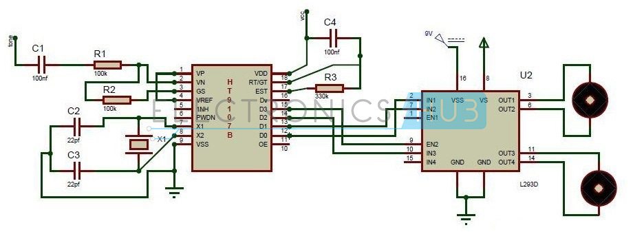
DTMF based Mobile Controlled Robotic Vehicle without using microcontroller
DTMF based Mobile Controlled Robot Circuit Diagram
Circuit Components:
  • DTMF Decoder IC (HT9107B)
  • Motor Driver IC
  • Motors
  • Resistors – R1, R2 & R3
  • Capacitors – C1 to C4
  • Crystal Oscillator

DTMF Controlled Robot Circuit Design:

The main components of the circuit are DTMF decoder IC, motor driver IC and motors. The decoder IC used here is HT9107B IC. The second pin of decoder IC is an inverting pin of the operational amplifier.
Tone is applied to the IC through a series of capacitor and resistor. The output of the Op Amp is feed back through GS pin of the IC. An external crystal is connected to the 7th and 8th pins of the IC.
Motor driver IC used is L293D. It has 16 pins. 2, 7, 10, 15 pins are the inputs of motor driver IC connected from output pins of the decoder IC. The output pins are 3, 6, 11, 14. These pins are connected to the two motors of robotic vehicle. 8th pin is connected to the 5v. Vss is the input voltage with which the motors runs. Motors cannot be driven with 5Vof microcontroller. So, a driver IC is used to amplify this voltage. VSS pin provides this voltage.

How DTMF based Robotic Vehicle Circuit Works?

  • Arrange the robot mechanically i.e. connect the wheels to the motors, place the circuit on the robot with a mobile fixed to it.
  • Now press ‘5’ from your mobile, robot starts moving forward.
  • Now press ‘0’ from your mobile, robot starts moving backward.
  • Now press ‘2’ to rotate the robot in left direction.
  • Now press ‘8’ to rotate the robot in right direction.

DTMF Controlled Robotic Vehicle Circuit Applications:

  • DTMF robot with slight modifications can be used in industrial applications.
  • DTMF robot with human detector sensor can be used at the time of disasters like earth quake to detect the human under buildings.
  • DTMF robot with camera can be used in surveillance systems.

Limitations of DTMF Controlled Robotic Vehicle :

  • DTMF robot may not work properly if it is operated with another mobile when there is no signal.
  • Mobiles with particular jacks are only used.

Thursday, 27 November 2014

Korean Companies Taking Lead in EV Battery Market

Korean Companies Taking Lead in EV Battery Market


An increasing number of carmakers such as Nissan and Daimler are opting for Korean battery manufacturers’ products instead of doing the lithium-ion secondary battery business on their own. The trend is expected to be a boon for LG Chem, Samsung SDI, and SK Innovation in the fledgling eco-friendly car battery market.
The only German factory that produces battery cells for electric cars is closing. Within little more than one year, the company Li-Tec in Saxon Kamenz, will cease manufacture of battery cells. The company is a subsidiary of the Daimler Group.
The Li-Tec factory will close December 2015 but will be retained as a research location; the majority of the 280 employees will be transferred to the Deutsche Accumotive—also a wholly owned Daimler subsidiary—which manufactures battery packs. Accumotive is currently expanding its production capacity to build systems for the next generation of the electric smart among others. Cells are slated to come from LG Chem.
“Nissan has purchased EV batteries from AESC since 2009, but will diversify the supply sources to LG Chem and many more,” Renault Nissan Alliance Chairman Carlos Ghosn said in September. It is said that AESC’s products are approximately 15 percent more expensive than those of LG Chem.
These decisions come about because it is difficult for a company to realize the economy of scale and achieve price competitiveness on its own in the eco-friendly vehicle market. Battery manufacturers that have produced small batteries for use in smartphones and the like have more advanced technological strength, too. It is in this context that Hyundai Motor Company, Kia Motors, and BMW have procured battery cells from external sources from the get go.
At present, LG Chem’s customers include not only Hyundai and Kia but also about 20 automakers such as GM and Ford. Samsung SDI has done business with about 10, including BMW, as well. SK Innovation, which started relatively late, has supplied batteries for Kia Motors’ Soul EV, and set up a joint venture in China with the Beijing Automotive Group. The EV battery market is estimated to grow to US$11.9 billion by 2018

Sydney International Airport Tests the World’s Longest Range Electric Bus

Sydney International Airport Tests the World’s Longest Range Electric Bus


Carbridge Pty Ltd, an Australian airport ground transportation provider, has begun a six-month Electric Bus pilot program at Sydney International Airport. The bus selected for the pilot was made by BYD Company Ltd, which has been recognized over the past few months for its industry leading operational range. The bus will be used as an airport passenger shuttle.
At a launch ceremony held at Sydney International Airport, BYD Asia Pacific General Manager Liu Xueliang said, “Compared with fossil-fueled buses, BYD’s pure electric bus has zero emissions, doesn’t make noise and ensures a comfortable ride without disturbances associated with conventional buses of combustion engines. These characteristics will provide a great experience for visitors to the Airport.” Sydney Airport plans to electrify their entire bus fleet in the coming years.
BYD’s Battery Electric bus employs many advanced technologies developed in-house by a staff of more than 15,000 R&D engineers, such as the advanced environmentally friendly, BYD Iron-Phosphate battery, in-wheel hub motors and regenerative braking system. The break-through Iron-Phosphate battery is fire-safe and non-toxic: there are no caustic materials contained in the battery, no toxic electrolytes or heavy metals and can be completely recycled.
The BYD electric bus delivers a host of operational and environmental benefits for public transport riders, operators and people in the community — it is very quiet and ensures a comfortable ride without vibrations, jerks or noise associated with the conventional buses and combustion engines. The bus can also drive for more than 250 km (155 miles) even in heavy city traffic on a single charge. The bus has completed more than 20 million kilometers of “in revenue service” and has been evaluated in many major cities all over the world.